Technical Questions
What's the difference between Laser Cutting and Water Jet Cutting?
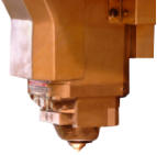
As a general rule, anything you can Laser cut, you laser cut, and if you can’t laser cut it you look at other methods like Water jet cutting. The reason for this is that laser will cut items faster (read cheaper) and with a better finish than water jet. However there are some specific things that the laser cannot cut or should not cut; For example; PVC, Teflon and Polycarbonate. Glass, ceramic, rubber and some foams. Products that are already painted, laminated products and composites do not cut well with laser. With laser we focus the beam of light to a point. This means the available thickness in any material is limited by the range of focal available for that material. Generally speaking, Aluminium greater than 10mm, Mild Steel greater than 16mm, Stainless Steel greater than 12mm all need to be cut by a method other than laser due to the focal limitations of the laser beam.
What are the usual lead times?
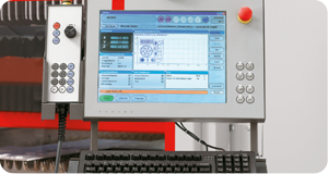
For existing parts, production is usually 2-4 working Days, for new parts you may need to allow approximately 5-7 Working Days. This is a guide only.
What can I get laser cut?
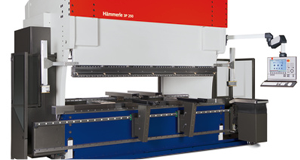
We can arrange the cutting of mild steel, stainless steel aluminium MDF, particle board, purspex, natural materials and many others. We can cut shapes and patterns so intricate that you would otherwise not be able to do with convetional cutting tools.
What is CNC Routing?
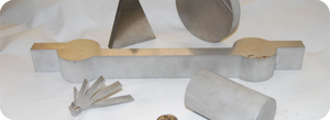
Routing has many applications outside of what can be lasercut, and can be especially good when cutting plastics. It is a traditional machining process using a spindle with a cutting tool, but combined with modern CAD/CAM systems complex shapes can be cut efficiently.
It has excellent squareness of edge and good finish characteristics.
It has some machine limitations; because we are cutting with a tool, you can’t have sharp internal corners, also the cutter is always trying to ‘throw’ the part, so material has to be clamped or ‘sucked’ down to the table.

Programming Problems
Vector vs. raster!!!!
I have to have a brief description of the polyline problem here, but it can get pretty complicated, so I will try to keep it simple!
Can I just point out here that the problem we are about to discuss is a geometric problem, it has nothing to do with computers or cutting machines, although computers can help solve the problem. If you are trying to generate curves on an old-fashioned drafting board and you need to define the arcs (as opposed to just drawing them freehand), you have the very same problem..
There are 2 types of curves:
Curves made up of defined geometry – circles or part of circles with a known centre and radius (also called True curves);
and Compound curves (also known as French curves) which are complex curves made up of mathematical formulae; (think sin curve…). Also included in this category are Splines, or approximated curves.
See picture of the sin curve, also x=y4
The reality of the cutting process is that no matter which type of curve you would like to cut, the machine itself can only cut True curves or straight lines, or a combination of both of these (also known as Vector data). This is true for all CNC machines that I have come across and is a function of the motion of the servo drives themselves.
However, if you need to cut a spline or complex curve there are ways that we can manipulate the data to produce some cutting. There are 2 methods used to approximate this data.
- Polyarcs (also known as ‘blended’ arcs)
- Polylines
Polyarcs are true arcs that have a known centre and radius that are blended from one arc to the next. They can be created manually, but the best result is to use some sign-writing software to generate them automatically. With good sign-writing software you will not see where one arc ends and the other begins. The problem is that the resultant arcs themselves are still only approximating the original polyline, and there may be minute variations from the original data. For Graphic design and signage purposes, this is not a problem, but from an engineering point of view this data can be considered erroneous to some degree.
See picture of the letter ‘D’
Polylines approach the problem from a different point of view. Instead of approximating the curves with True curves, the problem is solved by creating lots of smaller straight lines that join end to end. The idea is that if the lines are small enough, the original curve can be followed and the straight lines will not be too evident.
See picture of the previous ‘D’ with hex affect. x 2
The problem is that if the lines are too small, the CAM package that generates the code for the machine may not recognise the entities, or may treat the entities as points (even though in reality they have length). When the path hits a point it may turn around and go back in the other direction, or it may get caught in a ‘loop’ that sees it going backwards and forwards over the same entity that is little more than a dot. Then we ctl-alt-del to interrupt. Even if it does get all the way around, it may generate a file so big that it cannot be loaded on the machine, or, at the very least, cannot be edited on the machine. These files are generally cumbersome to handle.
The cutting machine itself will generally round the X and Y code to 2 decimal points, irrespective of how many decimal points are allowed when the CAD file was created. Once again it is those pesky servo drives.
Rounding of 2 decimal points to 0.1mm
Anything less than 0.1mm will be treated as a point by the machine itself, due to rounding. I would like to stress, the limiting factor is the machine itself, not the software that generates the code.
How do you generate Polyarcs and Polylines
The first thing you don’t do, is generate them with Graphic Design Software. I will say it again, do not use Graphic design software if you can avoid it. The two big players in the Graphic Design software market, Coreldraw and Adobe Illustrator do a really bad job of converting artwork which is made up of compound curves into lines for cutting. It looks great on the screen, but when we explode the complex curve in our CAD package, it breaks these complex curves into a godzillion entities. Try it yourself. Remember, we must break the complex curve into its entities, as the machine itself can only follow true arcs and lines (or vector data).
Why are sign-writing packages better?
There are a couple of simple reasons. One, they acknowledge that signage and lettering are mostly artistic and therefore the engineering precision that CAD packages demand is nor required. (This is one thing they have in common with Graphic design). Ie; when they are approximating a complex curve if there are slight variations in form it does not matter. (This is Art man…) The second reason is that most sign-writers nowadays have at least one vinyl-cutting machine in-house, and it uses exactly the same vector data that we require for our profile machines. The whole process of generating the lines and true curves is to create true vector data that the machine can read (which also goes for the vinyl cutting machine).
DO NOT use
- Graphic Design Software. (Corel Draw, Adobe Illustrator, etc.)
- 3D Modeling Software (Solidworks, Inventor, etc..)
- Engineering Software. (AutoCad, etc..)
DO use
- Sign Writing Programs (Sign-Lab, Sign Blazer, Sign Blaster, Flexi-Sign. etc..)
- Corel Conversion (Solution to Graphic Design Program problem)
- Signwriter Cleanup the file or Drawing over the top
Website By 3rd Floor Design Studio
